Test of the 2DoF digital PID controller
Description
In this example have been tested the functionalities of the 2DoF
incremental PID.
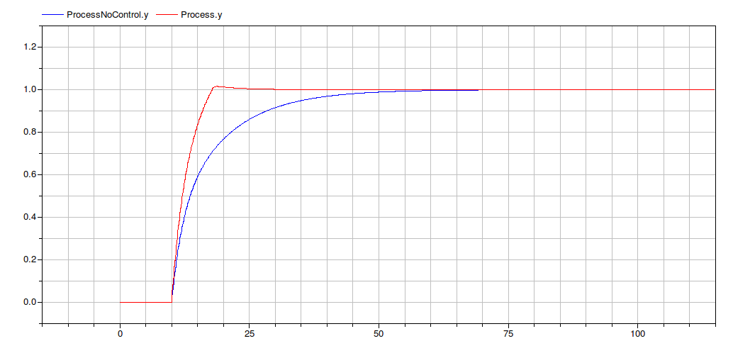
The PID has to control the process with transfer function
   Y(s)             5*s +1
   ----  =  -----------------------
   U(s)        20*s^2 + 12*s + 1
The image compares the outputs of the process y with and without the controller action.
Functionalities
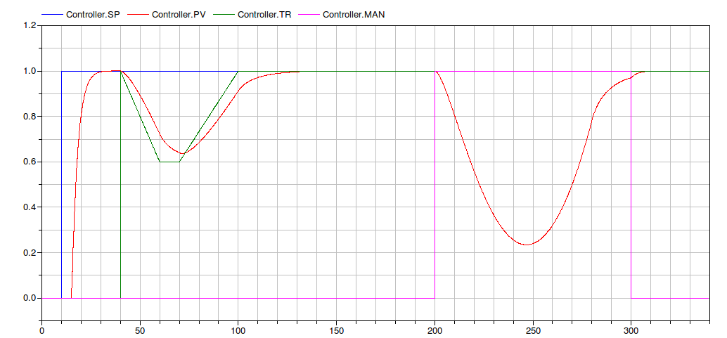
In the following figure are shown the functionalities of the block.
At the beginning the process variable
does not grows because the Finc signal
that forbid the CS increment is
true.
At t = 15 it becomes false and the PID start to act on the process,
leading the PV to the Set Point
desidered value.
At t = 40 the TS signal becomes true
and it is maintained until t = 130. In such a period the
Control signal follows the TR one (the green one). To note that at
the end the transition between Tracking and Automatic mode
is bumpless.
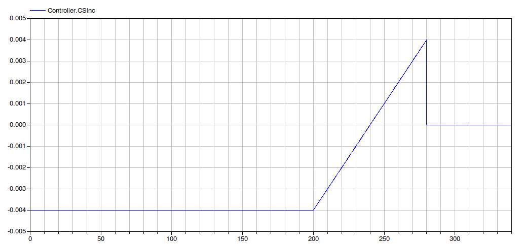
Between t = 200 and t = 300, the PID manual mode is enabled. In
this phase the Control Signal varies according to the CSinc signal
(see figure below).
- Industrial Control Systems (v 1.0.0) : April-May 2012
-
- List of revisions:
-
- 11 May 2012 (author: Marco Bonvini)
- Main Authors:
- Marco Bonvini; <bonvini@elet.polimi.it>
- Alberto Leva <leva@elet.polimi.it>
- Politecnico di Milano
- Dipartimento di Elettronica e Informazione
- Via Ponzio 34/5
- 20133 Milano - ITALIA -
- Copyright:
- Copyright © 2010-2012, Marco Bonvini and Alberto
Leva.
- The IndustrialControlSystems package is free
software; it can be redistributed and/or modified under the terms
of the Modelica license.
Generated at 2026-04-14T18:18:34Z by OpenModelicaOpenModelica 1.26.3 using
GenerateDoc.mos