
modelGpioEdge
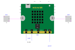
The edge pins as on the board: P1 drives P0 through a wire loop, the display mirrors the level read on P0
Extends from Modelica.Icons.Example (Icon for runnable examples).
Information
Expected result: P1 is driven high by the script (pin1.write_digital(1)), P0 reads it back through the wire loop: the plot of mb.P0.v stays at 3 V, and the matrix shows a dot at the bottom centre (level of P0 read by pin0.read_digital()).
The edge pins (pin0...pin20) are used exactly as on the physical board - the same program runs unchanged on a real micro:bit.
Components
| Type | Name | Default | Description |
|---|---|---|---|
| MicroPythonMCU.MicroBit_v2 | mb | Program: Resources/Scripts/MCU/microbit_gpio.py | |
| Modelica.Electrical.Analog.Basic.Ground | ground | ||
| Modelica.Electrical.Analog.Basic.Resistor | loopR | Wire loop between P1 (output) and P0 (input) | |
| Modelica.Blocks.Sources.BooleanConstant | btnA | button A idle | |
| Modelica.Blocks.Sources.BooleanConstant | btnB | button B idle |