
modelPartialMcuCore
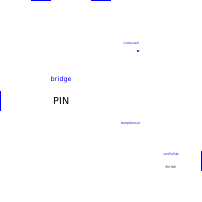
Extends from PartialMcuSettings (User parameters of a microcontroller (program, file system, execution time, debugging, electrical stages of the pins) - declared once, shared by the boards (MCU, RPi_Pico, MicroBit_v2) and their core Internal.Boards.McuCore).
Information
The programmable core, minus its sync point: embedded Python interpreter (PyRuntime), one electrical stage Internal.Boards.PinBridge per pin, power-on logic. The boards instantiate McuCore, which adds the sync point (PyRuntime_sync). Its parameters are those of the board that contains it (Internal.Boards.PartialMcuSettings), plus the pin table (nPins, pinIds, pinCaps, boardProfile) set by the board.
- Pins
pin[nPins]: push-pull outputs fed byvdd— their high level is the voltage ofvdd, and their current is drawn from it. - Supply
vdd/gnd: the core drawsICorewhile supplied. - Power-on:
powerGood=vddaboveVPowerOn(down toVPowerOff, hysteresis) andrunhigh (internal pull-up, may stay unconnected). The program starts at the first supplied sync point,time.ticks_ms()counting from there; a later loss stops it for good (no restart), pins in high impedance. - ADC reference
vref: high impedance input. - Temperature sensor (
hasTempSensor): an extra ADC channel at the end of the pin table (pseudo-pin 30,ADC(4)on the pico profile), 0.706 V at 27 °C, −1.721 mV/°C.
See requirements.md, decisions "Carte Raspberry Pi Pico et alimentation" and "Refactoring du socle des cartes".
Parameters
| Type | Name | Default | Description |
|---|---|---|---|
| Modelica.Units.SI.Time | tickPeriod (from PartialMcuSettings) | 0.1 | Period of the minimal sync point (output freshness if the script never sleeps) |
| Integer | nPins | Number of pins of the core (external pins, internal pins of the board, on-board LED) - at most 31 (MAX_PINS on the C side, minus the temperature sensor) | |
| Integer[nPins] | pinIds | GPIO number of each pin, as written in the script | |
| Integer[nPins] | pinCaps | Capabilities of each pin: sum of 1 = digital (Pin, PWM), 2 = wired to a connector (UART, I2C, I2CTarget), 4 = ADC input | |
| String | boardProfile | "generic" | Board profile read by the machine shim: "generic" (MCU), "pico" (RPi_Pico) or "microbit" (MicroBit_v2) |
| Boolean | hasTempSensor | false | On-chip temperature sensor, read by machine.ADC(4) on the pico profile |
| Modelica.Units.NonSI.Temperature_degC | dieTemperature | 27 | Temperature of the chip, read by the temperature sensor |
| Modelica.Units.SI.Current | ICore | 0.02 | Current drawn from vdd by the core and its flash while supplied (pins excluded) |
| Modelica.Units.SI.Voltage | VPowerOn | 1.8 | Voltage of vdd above which the core starts (power-on reset) |
| Modelica.Units.SI.Voltage | VPowerOff | 1.6 | Voltage of vdd below which a running core stops for good (brown-out) |
| Modelica.Units.SI.Resistance | RRunPullUp | 50e3 | Internal pull-up of the RUN pin to vdd |
| String | instanceName | getInstanceName() | Name shown in the log and given to the copy of the flash: that of the board containing the core, set by it |
| Python script | |||
| String | scriptPath (from PartialMcuSettings) | Modelica.Utilities.Files.loadResource("modelica://MicroPythonMCU/Resources/Scripts/MCU/demo.py") | Path of the user script (.py) - with an active file system, run after boot.py instead of main.py; empty = main.py from the flash |
| Boolean | addScriptDirToPath (from PartialMcuSettings) | true | Make the .py files next to the script importable (e.g. import my_module) - mimics the real Pico (flash root folder on sys.path) |
| String | libraryPath (from PartialMcuSettings) | "" | Optional: a .py file from a shared library folder to make importable (the folder containing this file is added to the module search path) - leave empty if unused |
| File system › Simulated flash | |||
| Boolean | fsEnabled (from PartialMcuSettings) | false | Enable the file system (simulated flash) - disabled: open() and os raise OSError |
| String | fsSource (from PartialMcuSettings) | "" | Initial image of the flash (folder: data, boot.py, main.py, lib/), copied at each simulation and never modified - any file of the folder, the folder path or a modelica:// URI; empty = blank flash, only the script runs |
| String | fsWorkspace (from PartialMcuSettings) | "." | Workspace: folder where each simulation creates its copy, named <instance>_<FS name>_<date>_<time> (created if missing) - "." or relative path = from the simulation folder; full path of the copy shown in the log |
| Boolean | fsOpenExplorer (from PartialMcuSettings) | true | Open Windows Explorer on the copy at the end of the simulation |
| Execution time | |||
| Modelica.Units.SI.Time | gpioOpTime (from PartialMcuSettings) | 5e-6 | Execution time of a pin access (Pin.value(), on(), off()): two writes without sleep() give a pulse of this width (bit-banging) - order of magnitude of MicroPython on RP2040; 0 = instantaneous accesses |
| Modelica.Units.SI.Time | hangWarningTime (from PartialMcuSettings) | 10 | Real (wall-clock) time after which a warning is logged if the script does not let the simulation advance (loop without sleep() nor pin access, or with gpioOpTime = 0) - the simulation keeps waiting; 0 = no warning |
| Debugging | |||
| Boolean | debugEnabled (from PartialMcuSettings) | false | Debug the program with VS Code: at the start of the simulation, the microcontroller waits until VS Code attaches (debugpy, Run and Debug > attach to localhost:debugPort); simulated time stays frozen while the program is paused - one microcontroller per model |
| Integer | debugPort (from PartialMcuSettings) | 5678 | Local TCP port on which the debugger (debugpy) listens - the port of the VS Code attach configuration |
| Electrical › Logic levels | |||
| Modelica.Units.SI.Voltage | VOL (from PartialMcuSettings) | Interfaces.VOL | Logic low voltage |
| Modelica.Units.SI.Voltage | VIH (from PartialMcuSettings) | Interfaces.VIH | Threshold above which an input reads high |
| Modelica.Units.SI.Voltage | VIL (from PartialMcuSettings) | Interfaces.VIL | Threshold below which an input reads low |
| Electrical › Output stages | |||
| Modelica.Units.SI.Resistance | ROut (from PartialMcuSettings) | Interfaces.ROut | Output series resistance (drive strength) |
| Electrical › Input stages | |||
| Modelica.Units.SI.Resistance | RPullUp (from PartialMcuSettings) | Interfaces.RPull | Internal pull-up resistor to the supply, switched on by Pin(n, mode, Pin.PULL_UP) and by I2C() on SCL/SDA |
| Modelica.Units.SI.Resistance | RPullDown (from PartialMcuSettings) | Interfaces.RPull | Internal pull-down resistor to GND, switched on by Pin(n, mode, Pin.PULL_DOWN) |
| Modelica.Units.SI.Conductance | GOff (from PartialMcuSettings) | Interfaces.GOff | Leakage of a pin that does not drive its line (input, released I2C line), towards GND: 1e-9 S = 1 GOhm |
Connectors
| Type | Name | Default | Description |
|---|---|---|---|
| Modelica.Electrical.Analog.Interfaces.PositivePin[nPins] | pin | Pins of the core, in the order of pinIds | |
| Modelica.Electrical.Analog.Interfaces.PositivePin | vdd | Supply of the core and of its pins (IOVDD): high level of the outputs, pull-ups, consumption ICore | |
| Modelica.Electrical.Analog.Interfaces.NegativePin | gnd | Ground | |
| Modelica.Electrical.Analog.Interfaces.PositivePin | vref | Reference voltage of the ADC: read_u16() = 65535 at this voltage | |
| Modelica.Electrical.Analog.Interfaces.PositivePin | run | Enable (RUN), pulled up to vdd inside the core: to ground, the core is stopped for good - may stay unconnected | |
| Interfaces.DisplayLinkOutput | Display0 | Logical link to an educational display peripheral (machine.Display(0).write()) |
Components
| Type | Name | Default | Description |
|---|---|---|---|
| Boolean | powerGood | The core is supplied (vdd above the power-on threshold, RUN high): its program starts the first time this becomes true and stops for good when it falls back. start = false: pins in high impedance during the initialization, where they are all inputs anyway (see pre(powerGood) below) | |
| Boolean | supplyOk | vdd above the power-on threshold, with hysteresis | |
| Boolean | runHigh | RUN high |