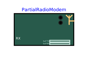
modelPartialRadioModem
Extends from PartialUartPins (Electrical side of a serial device: TX output and RX input on two pins, common ground, optional VCC pin - shared by the serial devices and the radio modems).
Information
Base class of the transparent radio modems. It cannot be instantiated directly: see Peripherals.Radio.RadioModem.
The modem is connected electrically to two GPx pins of an MCU (machine.UART), and to the other module(s) by one antenna wire. What it receives on its UART leaves on air, and what it hears on air comes out on its UART:
- a byte received from the microcontroller waits in the transmit buffer (
txBufferSizebytes) at leasttxDelay, then leaves in a radio frame of 8N1 type atairBaudrate, possibly different from the serial speed; - a radio frame heard intact waits in the receive buffer (
rxBufferSize) at leastrxDelay, then leaves on the UART; - a byte that finds its buffer full is lost; a corrupted radio frame (different air data rates, for example) is dropped, as by a real module that checks its packets; in half duplex, a frame arriving while the module transmits is lost.
Masked synchronisation. The receiver does not demodulate sTx: the antenna wire also carries the bit being transmitted, which the receiver decodes as a real serial receiver would, at its own air data rate. The modulated signal is drawn for teaching purposes, with a scaled carrier (fDisplay) since a real carrier cannot be drawn; to see it, reduce the output interval of the simulation well below 1/fDisplay. A receiver only hears a transmitter on its channel (fCarrier within half a channelWidth) and with its modulation.
The icon shows the radio frames being transmitted (amber dot) and received (cyan dot) and the filling of the two buffers, while replaying a result with animation in OMEdit. At the end of the simulation, each module writes a summary line in the log: bytes passed, bytes lost and why.
Parameters
| Type | Name | Default | Description |
|---|---|---|---|
| Electrical › Supply | |||
| Boolean | useSupplyPin (from PartialSupplyPin) | false | Show the VCC supply pin: the peripheral is supplied by the circuit (its high levels follow VCC, its consumption IQ is drawn from VCC) - unchecked: ideal internal supply VOH, nothing to wire |
| Modelica.Units.SI.Voltage | VOH (from PartialSupplyPin) | Interfaces.VOH | Logic high voltage: ideal internal supply, high level of the outputs and of the pull-ups - with the VCC pin, the voltage of VCC is used instead |
| Modelica.Units.SI.Current | IQ (from PartialSupplyPin) | 1e-3 | Current drawn from VCC by the peripheral (quiescent consumption, outputs excluded) |
| Boolean | useGroundPin (from PartialSupplyPin) | true | Show the GND pin - unchecked: the peripheral is referenced to the simulation ground (0 V), nothing to wire |
| Electrical › Levels | |||
| Modelica.Units.SI.Voltage | VOL (from PartialUartPins) | Interfaces.VOL | Logic low voltage |
| Modelica.Units.SI.Voltage | VIH (from PartialUartPins) | Interfaces.VIH | Threshold above which an input reads high |
| Modelica.Units.SI.Voltage | VIL (from PartialUartPins) | Interfaces.VIL | Threshold below which an input reads low |
| Electrical › Impedances | |||
| Modelica.Units.SI.Resistance | ROut (from PartialUartPins) | Interfaces.ROut | Output series resistance |
| Modelica.Units.SI.Resistance | RPullUp (from PartialUartPins) | 1e6 | Pull-up of the RX input to the supply |
| Electrical › Pins | |||
| Boolean | useTxPin (from PartialUartPins) | true | Show the TX pin - unchecked for a device that never transmits (its output stage then stays unconnected) |
| Serial link (microcontroller side) | |||
| Integer | baudrate | 9600 | Speed of the serial link with the microcontroller, in baud |
| Integer | dataBits | 8 | Number of data bits of a serial frame (5 to 8, as machine.UART bits=) |
| Interfaces.UartParity | parity | Interfaces.UartParity.None | Parity of a serial frame (as machine.UART parity=: None, 0 = even, 1 = odd) |
| Integer | stopBits | 1 | Number of stop bits of a serial frame (1 or 2, as machine.UART stop=) |
| Radio | |||
| Interfaces.Modulation | modulation | Interfaces.Modulation.FSK | Modulation of the carrier by the bits of the radio frame - a receiver only hears a transmitter using the same one |
| Modelica.Units.SI.Frequency | fCarrier | 434e6 | Nominal carrier frequency (channel) - a receiver only hears a transmitter whose carrier is within half a channel width of its own |
| Modelica.Units.SI.Frequency | channelWidth | 200e3 | Width of the channel heard around fCarrier |
| Integer | airBaudrate | 9600 | Air data rate, in bit/s - radio frame 8N1, independent of the serial link; both modules must use the same |
| Boolean | halfDuplex | true | Deaf while transmitting: a frame arriving during our own transmission is lost (one radio channel cannot carry both directions at once) |
| Buffers and delays | |||
| Integer | txBufferSize | 256 | Transmit buffer (UART -> air), in bytes - a byte arriving from the UART while it is full is lost |
| Integer | rxBufferSize | 256 | Receive buffer (air -> UART), in bytes - a byte arriving from the air while it is full is lost |
| Modelica.Units.SI.Time | txDelay | 0.005 | Fixed delay between the end of a byte on the UART and its earliest transmission on air |
| Modelica.Units.SI.Time | rxDelay | 0.001 | Fixed delay between the end of a byte on air and its earliest transmission on the UART |
| Drawn signal › Drawn carrier | |||
| Modelica.Units.SI.Frequency | fDisplay | 4*airBaudrate | Scaled carrier used to draw sTx (a real one, hundreds of MHz, cannot be drawn). Default 4*airBaudrate = 4 periods per bit: 4.8 kHz at 1200 bit/s, 38.4 kHz at 9600 bit/s |
| Modelica.Units.SI.Frequency | deltaFDisplay | airBaudrate | FSK only: shift of the drawn carrier, fDisplay - deltaFDisplay for a 0, fDisplay + deltaFDisplay for a 1. Default airBaudrate: 3 and 5 periods per bit (28.8 and 48 kHz at 9600 bit/s) |
| Real | askLowAmplitude | 0.3 | ASK only: amplitude of the drawn carrier for a 0 (1 for a 1). 0 looks like OOK, 0.3 is clearly visible, above 0.7 a 0 is hard to tell from a 1 |
| Drawn signal › Simulation | |||
| Boolean | warnSampling | true | Warn in the log when the output interval is too long to draw the carrier: more than 1/(10*(fDisplay + deltaFDisplay in FSK)), i.e. 2.1 us at 9600 bit/s with the defaults |
| Modelica.Units.SI.Time | tickPeriod | 0.1 | Period of the minimal sync point: a safety net, the actual pace comes from the engine's deadlines |
Connectors
| Type | Name | Default | Description |
|---|---|---|---|
| Modelica.Electrical.Analog.Interfaces.NegativePin | GND (from PartialSupplyPin) | Common reference (ground), to be connected to the microcontroller's one - shown when useGroundPin is checked | |
| Modelica.Electrical.Analog.Interfaces.PositivePin | VCC (from PartialSupplyPin) | Supply of the peripheral (e.g. 3V3(OUT) of a Raspberry Pi Pico) - shown when useSupplyPin is checked | |
| Modelica.Electrical.Analog.Interfaces.PositivePin | TX (from PartialUartPins) | Transmission of the device - to be connected to the receive pin of the microcontroller - shown when useTxPin is checked | |
| Modelica.Electrical.Analog.Interfaces.PositivePin | RX (from PartialUartPins) | Reception of the device - to be connected to the transmit pin of the microcontroller | |
| Interfaces.Antenna | antenna | Antenna: connect it with ONE wire to the antenna of the module(s) to talk to |
Components
| Type | Name | Default | Description |
|---|---|---|---|
| Real | sTx | Modulated signal transmitted, drawn with the scaled carrier fDisplay (0 when not transmitting) - reduce the output interval to see the carrier | |
| Real | sRx | Signal of the other transmitter as received by this module, whatever its tuning (0 when no other module transmits) | |
| Boolean | carrierOn | carrierOnC | A radio frame is being transmitted |
| Boolean | airRxBusy | airRxBusyC | A radio frame is being received |
| Integer | txFill | txFillC | Bytes waiting in the transmit buffer (UART -> air) |
| Integer | rxFill | rxFillC | Bytes waiting in the receive buffer (air -> UART) |
| Integer | nSent | nSentC | Radio frames transmitted so far |
| Integer | nReceived | nReceivedC | Radio frames received intact so far |
| Integer | nDropped | nDroppedC | Bytes lost so far because a buffer was full |
| Integer | nCorrupted | nCorruptedC | Radio frames lost so far: corrupted (air data rate mismatch...), collided, or cut by our own transmission in half duplex |
| Boolean | heard | Exactly one other module transmits, on our channel and with our modulation: its frame reaches the decoder | |
| Boolean | collision | jam | Two other modules or more transmit at once: the frame being received is lost |