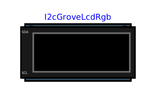
modelI2cGroveLcdRgb

Extends from Internal.Devices.PartialI2cDevice (Base of the I2C slave peripherals: open-drain electrical link, bus decoding, behaviour described by a Python script), Internal.Icons.Lcd16x2RgbIcon (Icon of a 16x2 character screen with RGB backlight: two-line text and background colour, animated while replaying a result).
Information
Twin of the Seeed Studio Grove - LCD RGB Backlight module: a 16x2 character screen whose backlight changes colour. The module carries two chips on the same I2C bus, hence two addresses for a single component:
0x3E— JHD1313, HD44780-compatible display controller: each byte is preceded by a control byte (0x80: command,0x40: character). Emulated commands: clear, return home, entry mode, display on/off, shift, function set, write position (line 1 at0x00, line 2 at0x40).0x62— PCA9633, 4-channel LED driver:MODE1/MODE2registers,PWM0–PWM3brightnesses (blue, green, red), group dimming,LEDOUT; auto-increment register pointer.
The behaviour is entirely described by Resources/Scripts/Device/grove_lcd_rgb.py, which follows the datasheets of both chips without knowing anything about the program driving them: a driver written for the real module works unchanged — see Examples.I2c.GroveLcd, which runs an off-the-shelf MicroPython driver without modification. Like the real controller, the screen is off at power-up and the backlight black: the program has to initialise them. A byte sent during a clear (1.52 ms) is ignored, with a warning in the log — on the real module, it would be lost.
The pull-up resistors of the bus are enabled (usePullUp = true), as on the real module. valueOut: red, green, blue intensities (0-255) and screen on (1/0); the icon takes this colour and shows the two visible lines while replaying a result with animation in OMEdit.
Hardware note: recent revisions of the module (v5) replace the PCA9633 with another LED driver, at another address. This component follows the PCA9633 at 0x62, which the reference driver targets; the address can still be changed through addresses (the script treats 0x3E as the screen and any other address as the LED driver).
Parameters
| Type | Name | Default | Description |
|---|---|---|---|
| Electrical › Supply | |||
| Boolean | useSupplyPin (from PartialSupplyPin) | false | Show the VCC supply pin: the peripheral is supplied by the circuit (its high levels follow VCC, its consumption IQ is drawn from VCC) - unchecked: ideal internal supply VOH, nothing to wire |
| Modelica.Units.SI.Voltage | VOH (from PartialSupplyPin) | Interfaces.VOH | Logic high voltage: ideal internal supply, high level of the outputs and of the pull-ups - with the VCC pin, the voltage of VCC is used instead |
| Modelica.Units.SI.Current | IQ (from PartialSupplyPin) | 1e-3 | Current drawn from VCC by the peripheral (quiescent consumption, outputs excluded) |
| Boolean | useGroundPin (from PartialSupplyPin) | true | Show the GND pin - unchecked: the peripheral is referenced to the simulation ground (0 V), nothing to wire |
| I2C bus | |||
| String | addresses (from PartialI2cDevice) | "0x42" | 7-bit address(es) the peripheral answers to, e.g. "0x42" or "0x3E, 0x62" (at most 4) |
| Boolean | usePullUp (from PartialI2cDevice) | false | Carry the pull-up resistors of SDA and SCL to the supply (at least one component of the bus must do it) |
| Modelica.Units.SI.Resistance | RPullUp (from PartialI2cDevice) | 4700 | Pull-up resistance of each line |
| Behaviour | |||
| String | scriptPath (from PartialI2cDevice) | "" | Script .py describing the behaviour (on_write / on_read / outputs / lines) |
| Inputs / outputs › Inputs (handler argument v) | |||
| Boolean | useValueInput (from PartialI2cDevice) | false | Take the quantities from the valueIn connector rather than from a constant |
| Integer | nIn (from PartialI2cDevice) | 1 | Number of quantities received from the model |
| Real | fixedValue (from PartialI2cDevice) | 0 | Value used when valueIn is not connected |
| Inputs / outputs › Outputs (return value of outputs()) | |||
| Integer | nOut (from PartialI2cDevice) | 1 | Number of quantities returned to the model by outputs() - leave the connector unconnected if unused |
| Electrical › Levels | |||
| Modelica.Units.SI.Voltage | VIH (from PartialI2cDevice) | Interfaces.VIH | Threshold above which an input reads high |
| Modelica.Units.SI.Voltage | VIL (from PartialI2cDevice) | Interfaces.VIL | Threshold below which an input reads low |
| Electrical › Impedances | |||
| Modelica.Units.SI.Resistance | ROut (from PartialI2cDevice) | Interfaces.ROut | Resistance of the SDA output transistor when it pulls the line to ground |
| Modelica.Units.SI.Conductance | GOff (from PartialI2cDevice) | 1e-9 | Leakage of the SDA output transistor when off (line released) |
| Modelica.Units.SI.Capacitance | CIn (from PartialI2cDevice) | 10e-12 | Input capacitance of each pin (SDA, SCL) |
| Modelica.Units.SI.Resistance | RIn (from PartialI2cDevice) | 10 | Series resistance of each pin (pad), between the bus wire and the input capacitance |
Connectors
| Type | Name | Default | Description |
|---|---|---|---|
| Modelica.Electrical.Analog.Interfaces.NegativePin | GND (from PartialSupplyPin) | Common reference (ground), to be connected to the microcontroller's one - shown when useGroundPin is checked | |
| Modelica.Electrical.Analog.Interfaces.PositivePin | VCC (from PartialSupplyPin) | Supply of the peripheral (e.g. 3V3(OUT) of a Raspberry Pi Pico) - shown when useSupplyPin is checked | |
| Modelica.Electrical.Analog.Interfaces.PositivePin | SDA (from PartialI2cDevice) | I2C bus data - to be connected to the SDA pin of the microcontroller and of the other peripherals | |
| Modelica.Electrical.Analog.Interfaces.PositivePin | SCL (from PartialI2cDevice) | I2C bus clock - to be connected to the SCL pin of the microcontroller and of the other peripherals | |
| Modelica.Blocks.Interfaces.RealInput[nIn] | valueIn (from PartialI2cDevice) | Quantities supplied by the model, passed to the script's handlers (argument v) | |
| Modelica.Blocks.Interfaces.RealOutput[nOut] | valueOut (from PartialI2cDevice) | Quantities returned by outputs() - the peripheral then becomes an actuator |
Components
| Type | Name | Default | Description |
|---|---|---|---|
| Boolean | sdaDriveLow (from PartialI2cDevice) | The peripheral pulls SDA to ground (acknowledge, or 0 bit read by the master) | |
| Boolean | busy (from PartialI2cDevice) | A phase addressed to this peripheral is in progress | |
| Integer | eventSeq (from PartialI2cDevice) | Incremented at each completed write or read phase | |
| String | lastEvent (from PartialI2cDevice) | Summary of the last completed phase (log) | |
| String | line1 (from PartialI2cDevice) | First line of text returned by lines() (displays) | |
| String | line2 (from PartialI2cDevice) | Second line of text returned by lines() | |
| Integer[16] | lcdLine1 (from Lcd16x2RgbIcon) | ASCII codes of visible line 1 - to be fed by the extending model, typically through Internal.Functions.StringToCharCodes | |
| Integer[16] | lcdLine2 (from Lcd16x2RgbIcon) | ASCII codes of visible line 2 | |
| Real[3] | backlight (from Lcd16x2RgbIcon) | Intensity of the red, green, blue backlight (0-255) - to be fed by the extending model |