Chassis Tutorial
Tutorial - Defining a new chassis model
The following process will demonstrate how to create a new
chassis model using these interface definitions. This tutorial will
guide you through building a chassis for a passenger car,
i.e., a vehicle with 4 wheels.
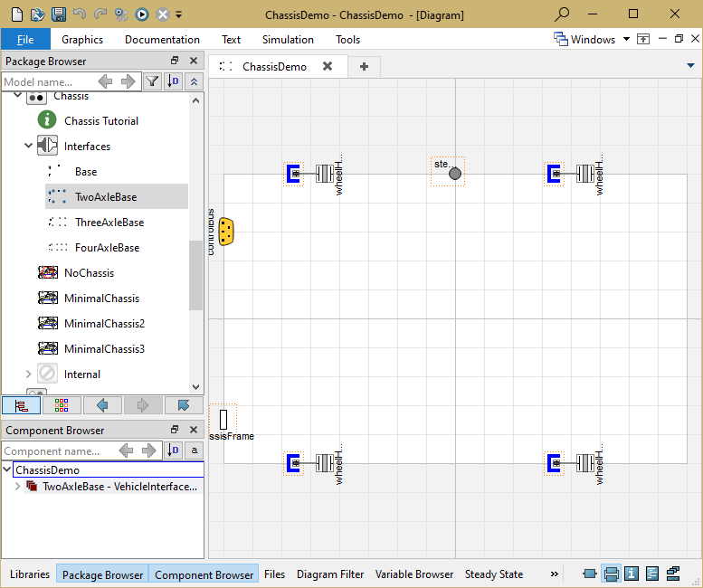
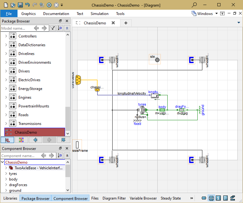
- Create a new model that extends TwoAxleBase,
it should look like this:
- In the component browser, right click on
TwoAxleBase and select Parameters
from the context menu to produce the following parameter
dialog
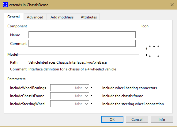
- This dialog allows you to enable/disable the optional
connections by setting includeWheelBearings,
includeSteeringWheel and
includeChassisFrame as required for your new
chassis model. The wheelHub connectors are of the type
Modelica.Mechanics.MultiBody.Interfaces.FlangeWithBearing, the
parameter includeWheelBearings controls whether
the bearing connectors within the wheelHubs is enabled or not.
- You can now define your chassis model as required
Creating a simple chassis model for longitudinal motion
The following steps demonstrate how to create a simple
chassis model for longitudinal motion. The chassis model will
transmit the torque from the wheel hub connections in to
a force being applied to the vehicle model. Only the
longitudinal dynamics of the vehicle body will be modelled so no
suspension is required.
Starting from step 3 above.
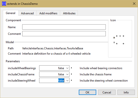
- First, decide which of the optional connectors are required in
the model. For this example we don't need any of the optional
connections
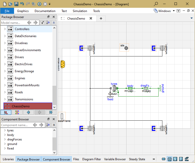
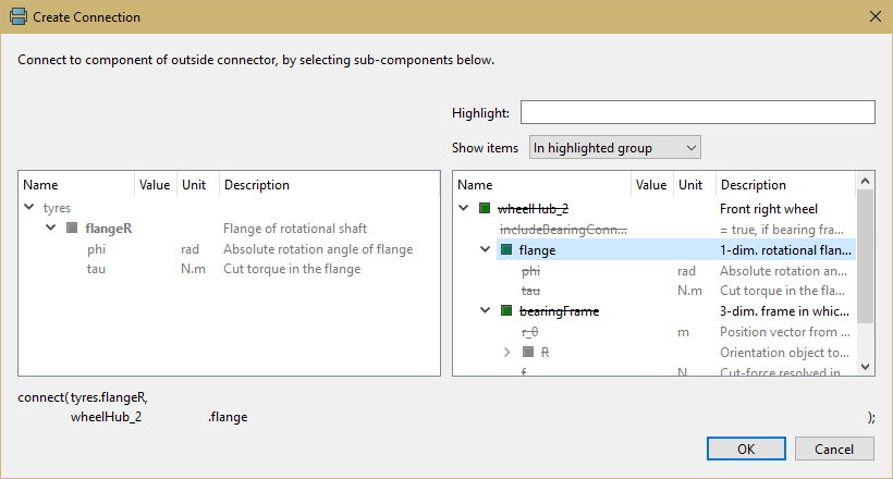
- Add the following blocks and connections to the diagram. When
you draw the connections to the wheelHub connectors the dialog box
shown below will appear asking which connector within the wheelHub
connector you would like to make the connection to. As we are
modelling the wheels as a 1D system you should select
flange from the list of options which is the 1D
connector within the wheelHub connector.
- Next, we need to check to see if any connections to the control
signal bus are required for the chassis, see here for
a complete list of the minimum connections required. In this
case we need to add the vehicle longitudinal velocity to the
control signal bus and this can be done by connecting a speed
sensor to the vehicle body and then connecting this to the signal
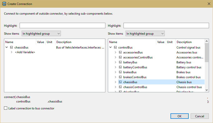
bus. As the longitudinal speed signals are added to the chassisBus
we first need to add this connector. The chassisBus connector is
VehicleInterfaces.Interfaces.ChassisBus.
This should be connected to the controlBus, when
this connection is made the following dialog is produced and should
be completed as shown.
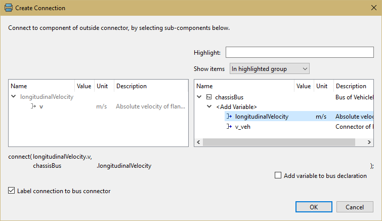
- When the connection between the sensor and the chassisBus
connector is added the dialog below appears and should be completed
as shown
- The model is now complete and should check successfully and can
be used in any model compatible with the VehicleInterfaces library
assuming the selected Driver model doesn't use the steering wheel
or chassis frame connections
Generated at 2026-04-14T18:18:34Z by OpenModelicaOpenModelica 1.26.3 using
GenerateDoc.mos