Engines Tutorial
Tutorial - Defining a new engine model
The following process will demonstrate how to create a new
engine model using this interface definition.
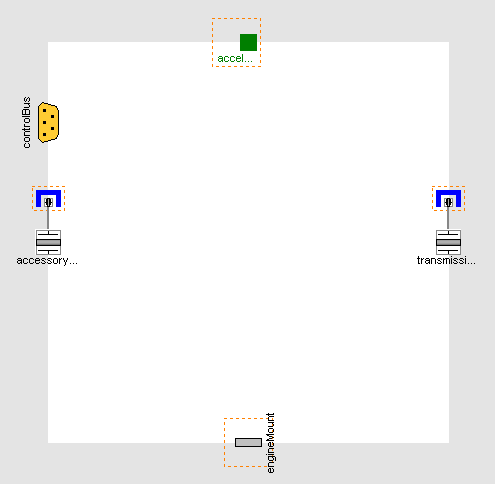
- Create a new model that extends
VehicleInterfaces.Engines.Interfaces.Base, it
should look like this:
- In the component browser, right click on Base
and select Parameters from the context menu to
produce the following parameter dialog
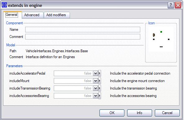
- This dialog allows you to enable/disable the optional
connections by setting includeAcceleratorPedal and
includeMount as required for your new engine
model. The accessoriesFlange and
transmissionFlange are of the type
Modelica.Mechanics.MultiBody.Interfaces.FlangeWithBearing, the
parameters includeTransmissionBearing and
includeAccessoriesBearing controls whether the
bearing connectors within these connections are enabled or
not.
- You can now define your engine model as required
Creating the MinimalEngine example
The following steps demonstrate how to create a simple
engine model. The engine model will apply torque at the flywheel
inertia based on a simple gain from the driver's accelerator
pedal. No torque reaction in to the engine block will be
modelled.
Starting from step 3 above.
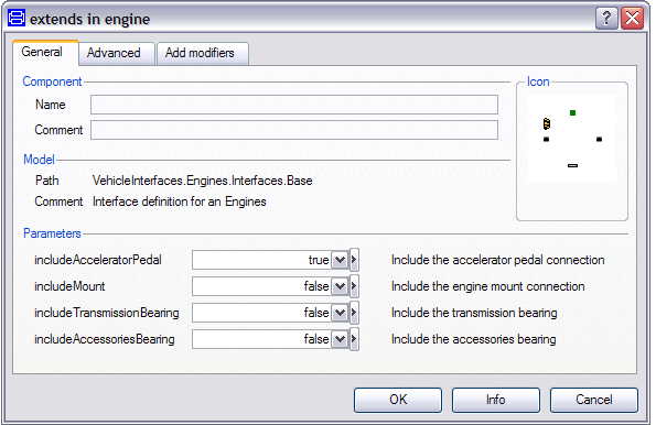
- First, decide which of the optional connectors are required to
model. For this example we need the accelerator pedal connection
but not the engine mount connection
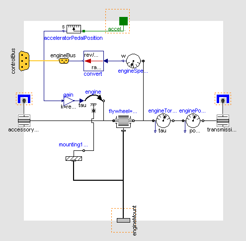
- Add the following blocks and connections to the diagram
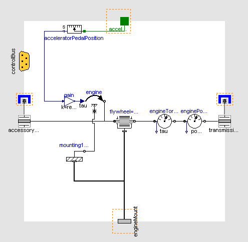
- Next, we need to check to see if any connections to the control
signal bus are required for the engine, see here for
a complete list of the minimum connections required. In this
case we need to add the engine speed to the control signal bus and
this can be done by connecting a speed sensor to the flywheel
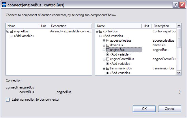
and then connecting this to the signal bus. As the engine speed
signal is added to the engineBus we first need to add this
connector. The engineBus connector is
VehicleInterfaces.Interfaces.EngineBus. This
should be connected to the controlBus, when this
connection is made the following dialog is produced and should be
completed as shown.
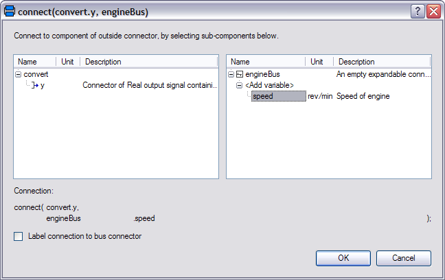
- We shouldn't connect the speed sensor directly to the engineBus
connector though because the units for the speed signal would be
incorrect. The definition of the speed signal on the control bus
also states that this should be in rev/min (or rpm) but the speed
sensor measures speed in rad/s. We can convert the
units using the conversion blocks that can be found in
Modelica.Blocks.Math.UnitConversions. Add
a conversion block to convert the output of the speed sensor
to rpm and connect this to the engineBus. When this connection is
made the following dialog will be produced and should be complete
as shown.
- The model is now complete and should check successfully and can
be used in any model compatible with the VehicleInterfaces library
assuming the selected Driver model also uses the accelerator pedal
connection
Generated at 2026-04-14T18:18:34Z by OpenModelicaOpenModelica 1.26.3 using
GenerateDoc.mos