The characteristic of the control valve can be selected using
the parameter typCha. The different choices are
defined by the enumeration
Buildings.Fluid.HydronicConfigurations.Types.ValveCharacteristic.
Each model includes an automatic sizing of the control valve based on the considerations provided in the model documentation and considering the two following criteria.
The sizing of the control valve may be disabled by setting the
parameter use_siz to false. When
disabled, the user must assign a value to
dpValve_nominal. When enabled, the user must assign a
value to dp1_nominal and/or dp2_nominal
depending on the configuration, respectively the pressure
differential on the primary side and the pressure drop of the
consumer circuit at design conditions.
Note that the sizing rules do not take into account the discrete sizes of control valves. Those are available with Kvs values which increase in a geometric progression, referred to as a Renard series (Petitjean, 1994): Kvs ∈ {1.0, 1.6, 2.5, 4.0, 6.3, 10.0, 16.0, ...}. The models from this package do not take into account those discrete sizes but rather consider that any pressure drop can be achieved at design conditions. Also, the models neither take into account the additional pressure drop of the reducers that are needed when the valve diameter is lower than the pipe diameter.
For configurations with a secondary distribution pump, the user
may choose whether to include the pump in the configuration model
or not, using the parameter typPum from the
enumeration Buildings.Fluid.HydronicConfigurations.Types.Pump.
When included, the user can further select the type of pump using
the same parameter. Additionally, the user can select the type of
pump model with the parameter typPumMod from the
enumeration
Buildings.Fluid.HydronicConfigurations.Types.PumpModel.
Each model includes an automatic sizing of the optional
distribution pump. By default the secondary pump is parameterized
at maximum speed with m2_flow_nominal and
dp2_nominal plus any additional pressure drop within
the hydronic configuration. The sizing of the pump may be disabled
by setting the parameter use_siz to
false. When disabled, the user must assign a value to
mPum_flow_nominal and dpPum_nominal,
respectively the mass flow rate and total pressure rise at design
conditions. When enabled, the user must assign a value to
dp1_nominal and/or dp2_nominal depending
on the configuration, respectively the pressure differential on the
primary side and the pressure drop of the consumer circuit at
design conditions.
A default pump characteristic is also provided, which goes through the design operating point and spans over 0 and twice the design flow rate at maximum speed. This default characteristic is based on a least squares polynomial fit of the characteristics from Buildings.Fluid.Movers.Data.Pumps.Wilo, see Figure 1.
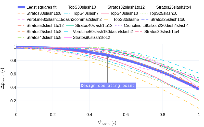
Figure 1. Pump normalized characteristics and least squares
polynomial fit.
The balancing valves are configured with zero pressure drop by default. The user may refer to the documentation of each configuration model for the specific balancing requirements, and assign the proper values to the corresponding parameters.
dpBal1_nominaldpBal2_nominaldpBal3_nominalPetitjean, R., 1994. Total hydronic balancing. Tour & Andersson AB, Ljung, Sweden.