The configurations are grouped together depending on the type of primary network they are compatible with. See Buildings.Fluid.HydronicConfigurations.UsersGuide.NomenclatureSymbols for the definitions of the different circuit types and the symbols used in the schematics below.
Example models using the configurations are provided in Buildings.Fluid.HydronicConfigurations.ActiveNetworks.Examples and Buildings.Fluid.HydronicConfigurations.PassiveNetworks.Examples. It is recommended that the user read the documentation of each example model carefully to understand their implementation, demonstration intent, and observations.
The following table presents the configurations compatible with such networks.
| Designation | Schematic | Application |
|---|---|---|
| Decoupling circuit with self-acting Δp control valve | 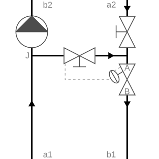 |
Used for variable flow primary and consumer
circuits where the consumer circuit has the same supply temperature
set point as the primary circuit. The fixed bypass prevents the
primary pressure differential from being transmitted to the
consumer circuit. This allows a proper operation of the terminal
control valves when the primary pressure differential is either too
low or too high or varying too much. The self-acting Δp control
valve maintains a nearly constant bypass mass flow rate. See Buildings.Fluid.HydronicConfigurations.ActiveNetworks.Decoupling for further details. |
| Decoupling circuit with ΔT control | 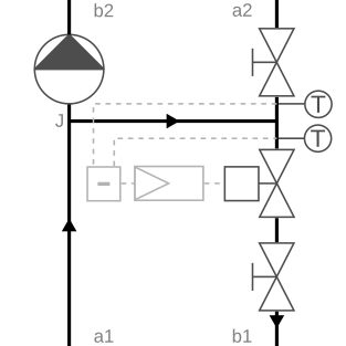 |
This configuration is nearly similar to Buildings.Fluid.HydronicConfigurations.ActiveNetworks.Decoupling except that an actuated control valve is used to control the ΔT between the secondary and primary return, ensuring a nearly constant fraction of flow recirculation in the bypass line. This configuration is not included in the package, see the example Buildings.Fluid.HydronicConfigurations.ActiveNetworks.Examples.DecouplingTemperature for a justification. |
| Diversion circuit | 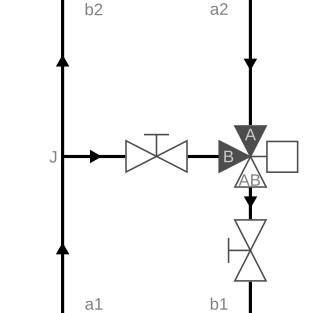 |
Used for constant flow primary circuits and
variable flow consumer circuits where the consumer circuit has the
same supply temperature set point as the primary circuit. See Buildings.Fluid.HydronicConfigurations.ActiveNetworks.Diversion for further details. |
| Injection circuit with three-way valve | 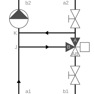 |
Used for constant flow primary and consumer
circuits where the consumer circuit has a different supply
temperature set point, either at design conditions or varying
during operation. Although this configuration may theoretically
still be used if the primary and secondary design temperatures are
equal, it loses its main advantage which is that the control valve
can be sized for a lower flow rate and can therefore be smaller.
The fixed bypass ensures a consumer circuit operation hydronically
decoupled from the primary side and the control valve
position. See Buildings.Fluid.HydronicConfigurations.ActiveNetworks.InjectionThreeWay for further details. |
| Injection circuit with two-way valve | 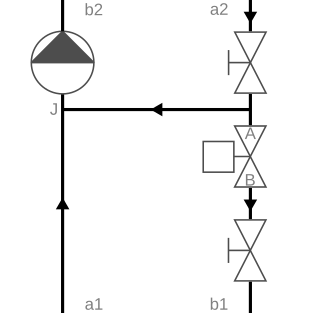 |
Used for variable flow primary circuits and either
constant flow or variable flow consumer circuits. The fixed bypass
prevents the primary pressure differential from being transmitted
to the consumer circuit. This allows a proper operation of the
terminal control valves on the consumer side when the primary
pressure differential is either too low or too high or varying too
much. See Buildings.Fluid.HydronicConfigurations.ActiveNetworks.InjectionTwoWay for further details. |
| Injection circuit with two-way valve and check valve in bypass branch | 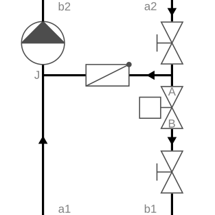 |
This configuration is nearly similar to
Buildings.Fluid.HydronicConfigurations.ActiveNetworks.InjectionTwoWay
except for the check valve that is added into the bypass. If used
in DHC systems and if the control valve is not properly sized to
maintain the set point at all loads, the check valve prevents
recirculation in the service line which degrades the ΔT in the
distribution system. If used to connect a heating coil, the check
valve reduces the risk of freezing in case of secondary pump
failure. See Buildings.Fluid.HydronicConfigurations.ActiveNetworks.InjectionTwoWayCheckValve for further details. |
| Single mixing circuit | 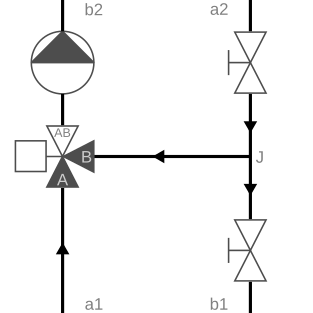 |
Used for variable flow primary circuits and either
constant flow or variable flow secondary circuits that have a
design supply temperature identical to the primary circuit but a
varying set point during operation. The control valve should be
sized with a pressure drop equal to the primary pressure
differential. That pressure drop must be compensated for by the
secondary pump which excludes the use of this configuration to
applications with a high primary pressure differential. See Buildings.Fluid.HydronicConfigurations.ActiveNetworks.SingleMixing for further details. |
| Throttle circuit | 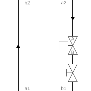 |
Used for variable flow primary and consumer
circuits that have the same supply temperature set point. See Buildings.Fluid.HydronicConfigurations.ActiveNetworks.Throttle for further details. |
The following table presents the configurations compatible with such networks.
| Designation | Schematic | Application |
|---|---|---|
| Dual mixing circuit | 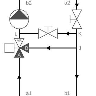 |
Used instead of
Buildings.Fluid.HydronicConfigurations.PassiveNetworks.SingleMixing
when the primary and secondary circuits have a different design
supply temperature. Contrary to the single mixing circuit, the use
of this configuration is restricted to constant flow secondary
circuits due to the constraint on the fixed bypass pressure
differential that must remain sufficiently high. See Buildings.Fluid.HydronicConfigurations.PassiveNetworks.DualMixing for further details. |
| Single mixing circuit | 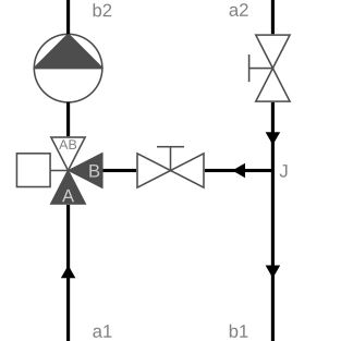 |
Used for variable flow primary circuits and either
constant flow or variable flow secondary circuits that have a
design supply temperature identical to the primary circuit but a
varying set point during operation. See Buildings.Fluid.HydronicConfigurations.PassiveNetworks.SingleMixing for further details. |