This block models the multi zone VAV AHU minimum outdoor air control with a single common damper for minimum outdoor air and economizer functions based on outdoor airflow measurement, designed in line with ASHRAE Guidline 36 (G36), PART 5.N.6.c.
The controller is enabled when the supply fan is proven on
(uSupFan=true), the AHU operation mode
Buildings.Obsolete.Controls.OBC.ASHRAE.G36_PR1.Types.OperationModes
equals occupied, and the freeze protection stage
Buildings.Obsolete.Controls.OBC.ASHRAE.G36_PR1.Types.FreezeProtectionStages
is stage1 or lower. Otherwise the damper position
limits are set to their corresponding maximum and minimum physical
or at commissioning fixed limits. The state machine chart below
illustrates listed conditions:

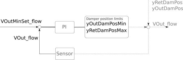
The controller sets the outdoor and return damper position
limits so that the outdoor airflow rate VOut_flow
stays equal or above the minimum outdoor air setpoint
VOutMinSet_flow. The fraction of the controller output
signal between yMin and uRetDamMin is
linearly mapped to the outdoor air damper minimal position
yOutDamPosMin while the fraction of the controller
output between uRetDamMin and yMax is
linearly mapped to the return air damper maximum position
yRetDamPosMax. Thus the dampers are not
interlocked.
The following control charts show the input/output structure and an expected damper position limits for a well configured controller.
The expected damper position limits vs. the control loop signal are as follows:
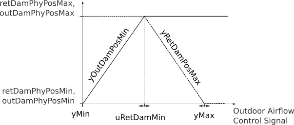
yMin to 0.