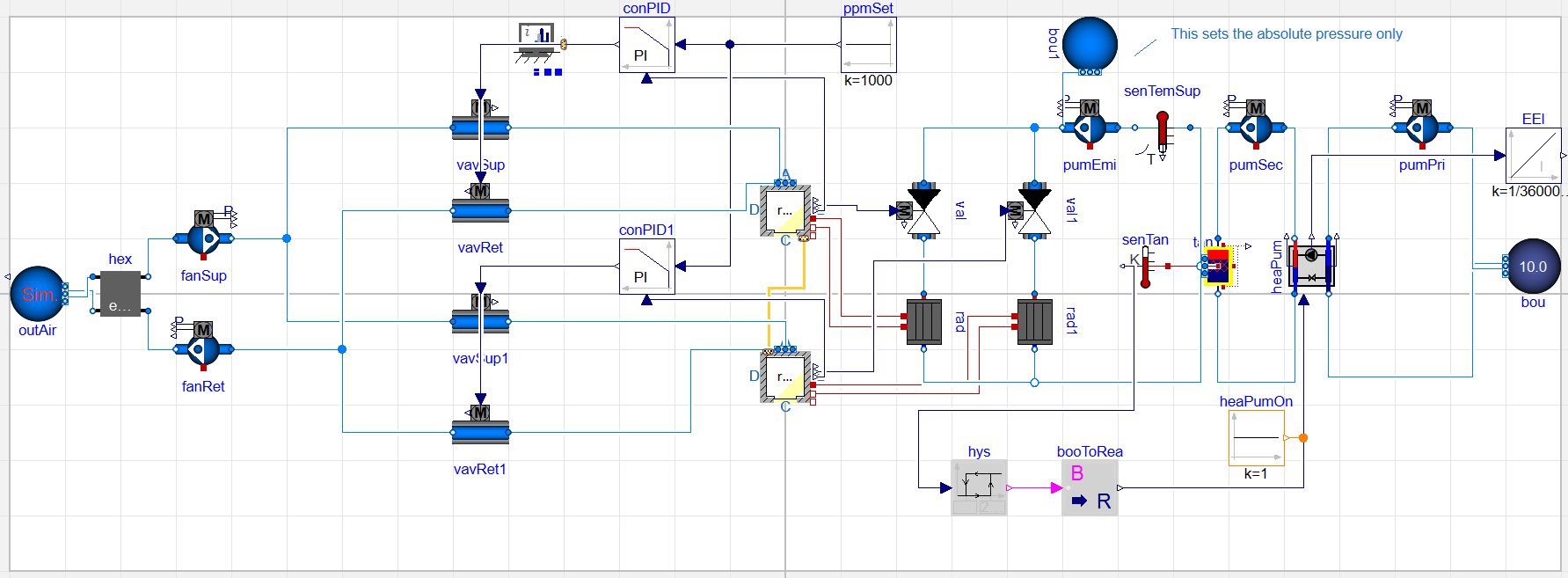
Adding CO2-controlled ventilation system. The occupancy model from IDEAS.Examples.Tutorial.DetailedHouse.DetailedHouse4 is added to one zone and a fixed occupancy of 1 person to the other zone. The ventilation system consists of two fans, two supply and two return air VAVs (Variable Air Volume), a heat recovery unit and an outdoor air source. The control consists of PI controllers with a setpoint of 1000 ppm.
This model extends from IDEAS.Examples.Tutorial.DetailedHouse.DetailedHouse8 where its existing medium declaration is modified to add CO2. For one zone, add the occupancy model from IDEAS.Examples.Tutorial.DetailedHouse.DetailedHouse4. For the other zone, a fixed occupancy of 1 person is added. For making a connection with the outside air IDEAS.Fluid.Sources.OutsideAir is used, which is similar to IDEAS.Fluid.Sources.Boundary_pT except that it automatically sets the outdoor dry bulb temperature and humidity.
For this exercise, assume that the VAV has a nominal flow rate
of 100 m3/h, which equals 0.033 kg/s. A
nominal pressure drop of 50 Pa is assumed and also
dpFixed_nominal=50, which causes the VAV model to
include a pressure drop of ducts, grills, filters or bends that are
connected at the inlet or outlet of the VAV. The fan pressure head
is constant at 200 Pa and its nominal flow rate is the sum
of the VAV flow rates. The heat recovery heat exchanger has a
constant effectiveness of 80 %.
The model includes two PI controllers, with their outputs
connected to the VAVs. The zone ppm outputs are
connected to the measurement inputs u_m of the PI
controllers, and a constant setpoint of 1000 ppm is provided
at the input u_s. The VAVs have a minimum opening of
10 %. The PI controllers are configured with the following
parameters: k = 0.005, T_i = 300,
reverseAction=false, and
controllerType=PI. The schematic representation of the
model is shown in the figure below.
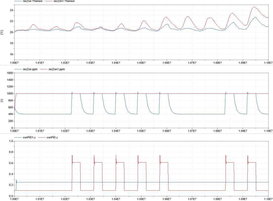
The figures below show the operative zone temperature, CO2 concentrations and PI control signals in both zones. Note the small overshoot of the PI controller outputs and the exponential decay towards the outdoor CO2 concentration when there are no occupants.