
modelPin
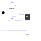
GP1 driven by a square wave (rising and falling edges); the script registers machine.Pin.irq() with trigger=IRQ_RISING on GP1, which toggles GP0 (LED) from the callback - proves the filtering by edge direction
Extends from Modelica.Icons.Example (Icon for runnable examples).
Information
Verification scenario 11 (see requirements.md): GP1 is driven by a square wave (Modelica.Blocks.Sources.Pulse, rising edge at t=2s/t=6s, falling at t=4s/t=8s). The script pin_irq_demo.py registers Pin(1, Pin.IN).irq(handler=on_rise, trigger=Pin.IRQ_RISING) — only a rising edge must trigger the callback, which toggles led0 (GP0). Expected result: GP0 toggles at t≈2s and stays unchanged at the falling edge of t≈4s (the LED stays on), proof that the filtering by edge direction works (not "any edge triggers"), then toggles again at t≈6s. Pins GP2-GP7, unused by this scenario, are left unconnected.
Components
| Type | Name | Default | Description |
|---|---|---|---|
| MCU | mcu | scriptPath = Verification/pin_irq_demo.py | |
| Modelica.Electrical.Analog.Basic.Ground | ground | ||
| Modelica.Electrical.Analog.Basic.Resistor | r0 | limits the current of led0 (GP0) | |
| MicroPythonMCU.Peripherals.LED | led0 | GP0: toggles on each rising edge of GP1 (IRQ_RISING) | |
| Modelica.Electrical.Analog.Sources.SignalVoltage | btnSrc | Drives GP1 from outside | |
| Modelica.Blocks.Sources.Pulse | pulseSrc | Square wave on GP1: rising edge at t=2s and t=6s, falling at t=4s and t=8s |