modelMCU
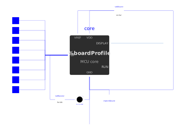
Extends from Internal.Boards.PartialBoard (Common base of the boards (MCU, RPi_Pico, MicroBit_v2): the user settings and the core contract are written here once - the boards add their pins, their connectors, their supply and their pin table (modifier of core in their extends)).
Information
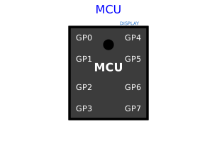
Simplified microcontroller with 8 pins and an ideal internal supply (VOH), made of the programmable core Internal.Boards.McuCore (inherited from the common base Internal.Boards.PartialBoard, also inside the board replicas RPi_Pico and MicroBit_v2), an ideal supply VOH and the on-board LED — see the internal diagram. The GND pin is shown by default; with useGroundPin unchecked ("Electrical" tab) it disappears and the microcontroller is referenced to the simulation ground (0 V), common to every Ground block. The core has one electrical stage per pin (Internal.Boards.PinBridge: push-pull output fed by the supply, switchable pulls, voltage sensing) controlled by PyRuntime, which runs the user's Python script (MicroPython-compatible, machine.Pin/machine.ADC/machine.PWM/time API) in a thread that intercepts sleep(). API reference: Raspberry Pi Pico (RP2040), see requirements.md — not shown on the icon, to stay generic. Each pin GP0-GP7 can be used, as the script chooses, as digital (machine.Pin), analog (machine.ADC, 16-bit reading of the voltage measured by the sensor already present in the bridge) or PWM (machine.PWM, square wave generated continuously on the Modelica side once frequency/duty cycle are set — no round trip with the Python thread at each edge, see requirements.md) — unlike the real Pico, where only some pins are ADC-capable, see the restrictions in requirements.md.
The script can import a helper module (import my_module): by default (addScriptDirToPath), the script's folder is added to the Python search path, and libraryPath can additionally designate a .py file of a shared library (its folder is then added too) — see requirements.md, decision "Import de modules auxiliaires".
File system (simulated flash, "File system" tab): disabled by default (fsEnabled), open() and os then raise OSError. When enabled, each simulation copies the fsSource folder (empty = blank flash) into a new folder of fsWorkspace ("." by default: the simulation folder), named <instance>_<FS name>_<date>_<time>; its full path is shown in the log at the start and at the end of the simulation, and Windows Explorer opens on it at the end (fsOpenExplorer). The script sees it as the root / of the flash: open() and the MicroPython-style os module (listdir, mkdir, remove, rename, stat, statvfs, chdir, getcwd...) are confined to it, and the root as well as /lib are on the import path. The source is never modified: each simulation starts again from the same state and stays deterministic (the timestamp only names the copy, the script does not see it). Program run, as on a board: boot.py from the flash if it exists, then scriptPath instead of main.py (like Thonny on an already booted board), or main.py from the flash if scriptPath is empty. See requirements.md, decision "Système de fichiers".
The electrical parameters (logic levels, output resistances) are grouped in the "Electrical" tab. The supply is ideal and implicit: VOH is the internal rail, i.e. the high level of the outputs and of the pull-ups; the microcontroller is always supplied. For a board with real supply pins and regulator, see RPi_Pico.
The Display0 connector exposes a logical link to an educational display peripheral (machine.Display(0).write(text)): unlike the GPx pins, it is not an electrical connector (Modelica.Electrical.Analog) but a causal logical connector (Interfaces.DisplayLinkOutput, message delivered instantly at the sync point, no serial waveform nor simulated baud rate) — to be connected to the displayLink (Interfaces.DisplayLinkInput) of a Peripherals.Display, an optional component (connect it or not, depending on the circuit). See requirements.md, decision "Périphérique d'affichage pédagogique".
The dot on the icon stands for the on-board LED of the Raspberry Pi Pico (wired to GP25 on the real board). It is handled like a normal pin, with the same electrical stage as GP0-GP7 (core.pin[9]) — only without an external connector: the output of this internal bridge permanently feeds a series resistance (ledResistor) and a real Peripherals.LED (builtinLed) connected to GND, true to the actual wiring of the Pico. It is driven from the script exactly like the 8 GPIO pins (machine.Pin(25, machine.Pin.OUT).on()/.off()); it is not one of the 8 exposed GPIO pins (see the restrictions in requirements.md), so no external circuit can be connected to it. Bright green when on, dark green otherwise — visible while replaying a simulation result with animation in OMEdit (DynamicSelect on builtinLed.mean.y), not on a static rendering.
Parameters
| Type | Name | Default | Description |
|---|---|---|---|
| Modelica.Units.SI.Time | tickPeriod (from PartialMcuSettings) | 0.1 | Period of the minimal sync point (output freshness if the script never sleeps) |
| Python script | |||
| String | scriptPath (from PartialMcuSettings) | Modelica.Utilities.Files.loadResource("modelica://MicroPythonMCU/Resources/Scripts/MCU/demo.py") | Path of the user script (.py) - with an active file system, run after boot.py instead of main.py; empty = main.py from the flash |
| Boolean | addScriptDirToPath (from PartialMcuSettings) | true | Make the .py files next to the script importable (e.g. import my_module) - mimics the real Pico (flash root folder on sys.path) |
| String | libraryPath (from PartialMcuSettings) | "" | Optional: a .py file from a shared library folder to make importable (the folder containing this file is added to the module search path) - leave empty if unused |
| File system › Simulated flash | |||
| Boolean | fsEnabled (from PartialMcuSettings) | false | Enable the file system (simulated flash) - disabled: open() and os raise OSError |
| String | fsSource (from PartialMcuSettings) | "" | Initial image of the flash (folder: data, boot.py, main.py, lib/), copied at each simulation and never modified - any file of the folder, the folder path or a modelica:// URI; empty = blank flash, only the script runs |
| String | fsWorkspace (from PartialMcuSettings) | "." | Workspace: folder where each simulation creates its copy, named <instance>_<FS name>_<date>_<time> (created if missing) - "." or relative path = from the simulation folder; full path of the copy shown in the log |
| Boolean | fsOpenExplorer (from PartialMcuSettings) | true | Open Windows Explorer on the copy at the end of the simulation |
| Execution time | |||
| Modelica.Units.SI.Time | gpioOpTime (from PartialMcuSettings) | 5e-6 | Execution time of a pin access (Pin.value(), on(), off()): two writes without sleep() give a pulse of this width (bit-banging) - order of magnitude of MicroPython on RP2040; 0 = instantaneous accesses |
| Modelica.Units.SI.Time | hangWarningTime (from PartialMcuSettings) | 10 | Real (wall-clock) time after which a warning is logged if the script does not let the simulation advance (loop without sleep() nor pin access, or with gpioOpTime = 0) - the simulation keeps waiting; 0 = no warning |
| Debugging | |||
| Boolean | debugEnabled (from PartialMcuSettings) | false | Debug the program with VS Code: at the start of the simulation, the microcontroller waits until VS Code attaches (debugpy, Run and Debug > attach to localhost:debugPort); simulated time stays frozen while the program is paused - one microcontroller per model |
| Integer | debugPort (from PartialMcuSettings) | 5678 | Local TCP port on which the debugger (debugpy) listens - the port of the VS Code attach configuration |
| Electrical › Logic levels | |||
| Modelica.Units.SI.Voltage | VOL (from PartialMcuSettings) | Interfaces.VOL | Logic low voltage |
| Modelica.Units.SI.Voltage | VIH (from PartialMcuSettings) | Interfaces.VIH | Threshold above which an input reads high |
| Modelica.Units.SI.Voltage | VIL (from PartialMcuSettings) | Interfaces.VIL | Threshold below which an input reads low |
| Modelica.Units.SI.Voltage | VOH | Interfaces.VOH | Logic high voltage: ideal internal supply, high level of the outputs and of the pull-ups |
| Electrical › Output stages | |||
| Modelica.Units.SI.Resistance | ROut (from PartialMcuSettings) | Interfaces.ROut | Output series resistance (drive strength) |
| Modelica.Units.SI.Resistance | ledSeriesR | 330 | Series resistance of the on-board LED (internal, GP25) |
| Electrical › Input stages | |||
| Modelica.Units.SI.Resistance | RPullUp (from PartialMcuSettings) | Interfaces.RPull | Internal pull-up resistor to the supply, switched on by Pin(n, mode, Pin.PULL_UP) and by I2C() on SCL/SDA |
| Modelica.Units.SI.Resistance | RPullDown (from PartialMcuSettings) | Interfaces.RPull | Internal pull-down resistor to GND, switched on by Pin(n, mode, Pin.PULL_DOWN) |
| Modelica.Units.SI.Conductance | GOff (from PartialMcuSettings) | Interfaces.GOff | Leakage of a pin that does not drive its line (input, released I2C line), towards GND: 1e-9 S = 1 GOhm |
| Power supply › Consumption | |||
| Modelica.Units.SI.Current | ICore (from PartialBoard) | 0.02 | Current drawn from the supply rail by the core and its memory while supplied (program running, pins excluded) |
| Power supply › Power-on | |||
| Modelica.Units.SI.Voltage | VPowerOn (from PartialBoard) | 1.8 | Supply rail voltage above which the core starts (power-on reset) |
| Modelica.Units.SI.Voltage | VPowerOff (from PartialBoard) | 1.6 | Supply rail voltage below which a running core stops for good (brown-out) |
| Electrical › Supply | |||
| Boolean | useGroundPin | true | Show the GND pin - unchecked: the microcontroller is referenced to the simulation ground (0 V), nothing to wire |
Connectors
| Type | Name | Default | Description |
|---|---|---|---|
| Modelica.Electrical.Analog.Interfaces.PositivePin | GP0 | GPIO 0 (machine.Pin(0), machine.ADC(0) or machine.PWM(0)) | |
| Modelica.Electrical.Analog.Interfaces.PositivePin | GP1 | GPIO 1 (machine.Pin(1), machine.ADC(1) or machine.PWM(1)) | |
| Modelica.Electrical.Analog.Interfaces.PositivePin | GP2 | GPIO 2 (machine.Pin(2), machine.ADC(2) or machine.PWM(2)) | |
| Modelica.Electrical.Analog.Interfaces.PositivePin | GP3 | GPIO 3 (machine.Pin(3), machine.ADC(3) or machine.PWM(3)) | |
| Modelica.Electrical.Analog.Interfaces.PositivePin | GP4 | GPIO 4 (machine.Pin(4), machine.ADC(4) or machine.PWM(4)) | |
| Modelica.Electrical.Analog.Interfaces.PositivePin | GP5 | GPIO 5 (machine.Pin(5), machine.ADC(5) or machine.PWM(5)) | |
| Modelica.Electrical.Analog.Interfaces.PositivePin | GP6 | GPIO 6 (machine.Pin(6), machine.ADC(6) or machine.PWM(6)) | |
| Modelica.Electrical.Analog.Interfaces.PositivePin | GP7 | GPIO 7 (machine.Pin(7), machine.ADC(7) or machine.PWM(7)) | |
| Modelica.Electrical.Analog.Interfaces.NegativePin | GND | Common reference (ground) - connect it to the ground of the external circuit - shown when useGroundPin is checked | |
| Interfaces.DisplayLinkOutput | Display0 | Logical link to an educational display peripheral (machine.Display(0).write()) - simplified causal link (message delivered instantly at the sync point), no real voltage/current nor bit-by-bit serial waveform, see requirements.md decision "Périphérique d'affichage pédagogique" |
Components
| Type | Name | Default | Description |
|---|---|---|---|
| Internal.Boards.PartialMcuCore | core (from PartialBoard) | Programmable core, public like in the boards so that its plotted variables (powerGood, supplyOk...) stay in the simulation results - partial: every board redeclares it (McuCore); pin table (nPins, pinIds, pinCaps), board profile and on-board devices are set by the board in the modifier of its extends, pins in the order of pinIds | |
| MicroPythonMCU.Peripherals.LED | builtinLed | On-board LED of the Raspberry Pi Pico (real GP25), wired inside the block (no external connector) |