
modelLink
Extends from Modelica.Icons.Example (Icon for runnable examples).
Information
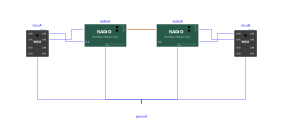
The serial link of Examples.MultiMcu.Uart, but by radio: each board is wired to a RadioModem with its default settings (TX of the board to RX of the module and the reverse, common ground), and the two modules are joined by one antenna wire. The programs are exactly the same as with a wired link: the modules are transparent. Board A (uart_ping.py) sends PING 0, PING 1, PING 2 and waits each time for the reply of board B (uart_pong.py); A sets GP7 high once every reply is right.
Plot mcuA.GP0.v (serial frames of A), radioA.carrierOn (radio frames of A) and mcuB.GP1.v (frames delivered to B): each line arrives a few milliseconds later than by wire — the 5 ms delay of the module, then the radio frame, then the 1 ms delay of the receiver. At the end, each module writes its summary in the log.
Drawn signal. Plot radioA.sTx and zoom on one radio frame (when radioA.carrierOn is true): in FSK, a 0 is drawn at 28.8 kHz and a 1 at 48 kHz (fDisplay = 4 × 9600 = 38.4 kHz, ± deltaFDisplay = 9600 Hz). sTx is only stored at the output points, hence the output interval of 2 µs of this example (about ten points per period at 48 kHz). The price: a result file of about 150 MB and a simulation about six times longer than with an interval of 100 µs. With 100 µs, one point per bit or so, the curve jumps at random between -1 and +1 (aliasing) although the link works. Raising fDisplay calls for an even shorter interval.
To change fDisplay from this model, write radioA(fDisplay = 16*radioA.airBaudrate), not 16*airBaudrate: a value entered in the parameter dialog is written in Link, where only radioA.airBaudrate exists. The default value 4*airBaudrate shown in grey is written in the radio module itself, where airBaudrate is a neighbouring parameter.
Components
| Type | Name | Default | Description |
|---|---|---|---|
| MCU | mcuA | Board A: Resources/Scripts/MCU/uart_ping.py (TX = GP0, RX = GP1) | |
| MCU | mcuB | Board B: Resources/Scripts/MCU/uart_pong.py (TX = GP0, RX = GP1) | |
| Peripherals.Radio.RadioModem | radioA | Radio module of board A (default settings, those of an APC220: 434 MHz, 9600 bit/s on air, 9600 baud) | |
| Peripherals.Radio.RadioModem | radioB | Radio module of board B, same settings | |
| Modelica.Electrical.Analog.Basic.Ground | ground |