
modelLoopback
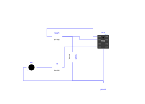
Extends from Modelica.Icons.Example (Icon for runnable examples).
Information
Demonstrates the machine.UART serial link as a real electrical signal: the TX pin carries a real frame (start bit at 0, 8 data bits least significant first, stop bit at 1), each bit lasting 1/baudrate. Plotting mcu.GP0.v lets you read the frame by eye in OMEdit, as on an oscilloscope.
The script waits 5 ms before transmitting, to show the idle state on the plot: as soon as the UART is configured, the TX pin is actively driven high ("mark" state), even before the first write(). The TX holds the line, not the RX — the output is push-pull, no pull-up resistor is involved (unlike an open-drain I²C bus).
The waveform is produced by the C runtime, which publishes the line level and only requests a sync point at its changes, without the Python thread driving each edge — like the real UART peripheral of the RP2040, which runs independently of the CPU once programmed (see requirements.md). Reception is decoded on the C side from the edges of the line, with the same mid-bit sampling as a real receiver.
The TX→RX loopback must reuse the loopR/loopC pattern of Examples.Gpio.PinEcho: connecting two pins of the same MCU with a direct connect() makes the driven voltage disappear from the simulation results.
Components
| Type | Name | Default | Description |
|---|---|---|---|
| MCU | mcu | scriptPath = Resources/Scripts/MCU/uart_loopback.py | |
| Modelica.Electrical.Analog.Basic.Ground | ground | ||
| Modelica.Electrical.Analog.Basic.Resistor | loopR | TX->RX loopback: link resistance. A direct connect() between two pins of the same MCU makes the driven voltage disappear from the simulation results (alias merge, observed empirically on Gpio.PinEcho) - worked around by giving RX a real dynamic state through loopC, see requirements.md | |
| Modelica.Electrical.Analog.Basic.Capacitor | loopC | Time constant of the loopback: (ROut + loopR)*C = 1.1 us, i.e. 0.13% of a bit at 1200 baud (833 us) - enough to avoid the exact algebraic alias, too little to distort the frame | |
| Modelica.Electrical.Analog.Basic.Resistor | r3 | limits the current of the reception indicator | |
| MicroPythonMCU.Peripherals.LED | led3 | GP3: lights up if the received byte is indeed the one transmitted |