modelLogicAnalyzer
Information
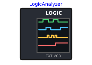
Probe of a logic analyser: connect its channels CH0…CH7 to lines of the circuit (a UART link, the SCL/SDA lines of an I2C bus, the clock and data lines of an HX711, a PWM output...) and its GND to the ground of the circuit, as with the clips of a real analyser (or uncheck useGroundPin, "Electrical" tab: the pin disappears and the probe is referenced to the simulation ground, 0 V). Each channel has a very high input impedance (GIn, 1 GΩ to ground): the circuit behaves the same with or without the probe.
Each channel has its own tab (CH0…CH7): a name and a kind (Interfaces.ChannelKind):
Off: not recorded, costs nothing, and its pin disappears from the icon. By default,CH0…CH3areLogicandCH4…CH7areOff: give a kind to a channel to make its pin appear. The names of the active channels are shown in green on the icon;Logic: logic level only — also the kind of a clock line;Uart: serial link decoded with the format of the tab (speed, data bits, parity, stop bits, bit order);I2cSda: SDA line of an I2C bus, whose SCL line is the channelclockChannel;SyncData: data of a synchronous serial link (HX711, simplified SPI), read on an edge of the channelclockChannel, in words ofwordBitsbits.
At the end of the simulation, the probe writes in the simulation folder, named after the component unless fileName is given (full paths in the log):
- a text file (
writeText), opened in Notepad ifopenTextis set: the decoded bytes of each channel in hexadecimal + ASCII (UART bursts, I2C transactions, synchronous words, summary of the logic channels), then an ASCII timing diagram of the channels, with the bits and bytes under each decoded waveform. The "Text file" tab chooses the sections, the frames on separate lines, the silences not drawn, the resolution and the width; - a VCD file (
writeVcd, Value Change Dump), opened in PulseView (free software of the sigrok project, with its own protocol decoders) ifopenPulseViewis set; GTKWave also reads it. Next to it, a PulseView session (writePulseViewSession,<base>.pvs) that PulseView loads by itself with the VCD file: its UART, I2C and SPI decoders are already set up from the channels (aSyncDatachannel is decoded as SPI).
With pulseViewPath empty (the default), the probe looks for PulseView in this order: the environment variable MICROPYTHONMCU_PULSEVIEW (path of pulseview.exe or of its folder, e.g. a copy on a network share), the portable copy fetched by get_pulseview.cmd into the PulseView folder next to the library, then the folder of the sigrok installer (C:/Program Files/sigrok/PulseView).
A level change is detected halfway between VIL and VIH; a level that changes and changes back at the same simulated instant is not recorded. Cost: one threshold-crossing function per channel that is not Off; on lines that already change at events of the model (outputs of the microcontroller or of a device), the probe adds no event of its own. The text file is written from the level changes kept in memory, without any extra event.
Parameters
| Type | Name | Default | Description |
|---|---|---|---|
| Files | |||
| String | fileName | "" | Base name of the files written in the simulation folder (<base>.vcd, <base>.txt); empty = name of the component (full paths shown in the log) |
| Boolean | writeText | true | Write the text file: decoded bytes in hex + ASCII and ASCII timing diagram (options in the "Text file" tab) |
| Boolean | openText | true | Open the text file in Notepad at the end of the simulation |
| Boolean | writeVcd | true | Write the VCD file (Value Change Dump), to be opened in PulseView or GTKWave |
| Boolean | writePulseViewSession | true | Write a PulseView session (<base>.pvs) next to the VCD file: PulseView, which loads it by itself with the VCD file, opens with its UART, I2C and SPI decoders already set up from the channels |
| Boolean | openPulseView | false | Open the VCD file in PulseView at the end of the simulation (a warning if PulseView is not found) |
| String | pulseViewPath | "" | Path of the PulseView executable (free software of the sigrok project): absolute path, path relative to the simulation folder, or modelica:// URI; empty = automatic search (environment variable MICROPYTHONMCU_PULSEVIEW, copy fetched by get_pulseview.cmd next to the library, then the sigrok installer folder) |
| CH0 › Channel | |||
| Interfaces.ChannelKind | ch0Kind | Interfaces.ChannelKind.Logic | Kind of channel CH0: Off, Logic (also for a clock line), Uart, I2cSda (SCL on clockChannel), SyncData (clock on clockChannel) |
| String | ch0Name | "" | Name of CH0 in the files (no comma); empty = CH0 |
| CH0 › UART | |||
| Real | ch0Baudrate | 1200 | Speed of the serial link (baud) |
| Integer | ch0DataBits | 8 | Data bits, from 5 to 8 |
| Interfaces.UartParity | ch0Parity | Interfaces.UartParity.None | Parity: None, Even or Odd |
| Integer | ch0StopBits | 1 | Stop bits, 1 or 2 |
| Interfaces.BitOrder | ch0UartBitOrder | Interfaces.BitOrder.LsbFirst | Bit order (a UART sends the least significant bit first) |
| CH0 › Clock (I2cSda, SyncData) | |||
| Integer | ch0ClockChannel | 1 | Number of the clock channel (SCL for I2cSda, clock for SyncData), itself of kind Logic |
| CH0 › Synchronous serial (SyncData) | |||
| Interfaces.ClockEdge | ch0ClockEdge | Interfaces.ClockEdge.Rising | Edge of the clock on which the data is read (HX711: Falling) |
| Integer | ch0WordBits | 8 | Bits per word (HX711: 24); the clock pulses left over are counted apart |
| Interfaces.BitOrder | ch0SyncBitOrder | Interfaces.BitOrder.MsbFirst | Bit order (HX711 and most SPI devices: most significant bit first) |
| Boolean | ch0Signed | false | Words in two's complement (HX711: true) |
| CH1 › Channel | |||
| Interfaces.ChannelKind | ch1Kind | Interfaces.ChannelKind.Logic | Kind of channel CH1: Off, Logic (also for a clock line), Uart, I2cSda (SCL on clockChannel), SyncData (clock on clockChannel) |
| String | ch1Name | "" | Name of CH1 in the files (no comma); empty = CH1 |
| CH1 › UART | |||
| Real | ch1Baudrate | 1200 | Speed of the serial link (baud) |
| Integer | ch1DataBits | 8 | Data bits, from 5 to 8 |
| Interfaces.UartParity | ch1Parity | Interfaces.UartParity.None | Parity: None, Even or Odd |
| Integer | ch1StopBits | 1 | Stop bits, 1 or 2 |
| Interfaces.BitOrder | ch1UartBitOrder | Interfaces.BitOrder.LsbFirst | Bit order (a UART sends the least significant bit first) |
| CH1 › Clock (I2cSda, SyncData) | |||
| Integer | ch1ClockChannel | 0 | Number of the clock channel (SCL for I2cSda, clock for SyncData), itself of kind Logic |
| CH1 › Synchronous serial (SyncData) | |||
| Interfaces.ClockEdge | ch1ClockEdge | Interfaces.ClockEdge.Rising | Edge of the clock on which the data is read (HX711: Falling) |
| Integer | ch1WordBits | 8 | Bits per word (HX711: 24); the clock pulses left over are counted apart |
| Interfaces.BitOrder | ch1SyncBitOrder | Interfaces.BitOrder.MsbFirst | Bit order (HX711 and most SPI devices: most significant bit first) |
| Boolean | ch1Signed | false | Words in two's complement (HX711: true) |
| CH2 › Channel | |||
| Interfaces.ChannelKind | ch2Kind | Interfaces.ChannelKind.Logic | Kind of channel CH2: Off, Logic (also for a clock line), Uart, I2cSda (SCL on clockChannel), SyncData (clock on clockChannel) |
| String | ch2Name | "" | Name of CH2 in the files (no comma); empty = CH2 |
| CH2 › UART | |||
| Real | ch2Baudrate | 1200 | Speed of the serial link (baud) |
| Integer | ch2DataBits | 8 | Data bits, from 5 to 8 |
| Interfaces.UartParity | ch2Parity | Interfaces.UartParity.None | Parity: None, Even or Odd |
| Integer | ch2StopBits | 1 | Stop bits, 1 or 2 |
| Interfaces.BitOrder | ch2UartBitOrder | Interfaces.BitOrder.LsbFirst | Bit order (a UART sends the least significant bit first) |
| CH2 › Clock (I2cSda, SyncData) | |||
| Integer | ch2ClockChannel | 1 | Number of the clock channel (SCL for I2cSda, clock for SyncData), itself of kind Logic |
| CH2 › Synchronous serial (SyncData) | |||
| Interfaces.ClockEdge | ch2ClockEdge | Interfaces.ClockEdge.Rising | Edge of the clock on which the data is read (HX711: Falling) |
| Integer | ch2WordBits | 8 | Bits per word (HX711: 24); the clock pulses left over are counted apart |
| Interfaces.BitOrder | ch2SyncBitOrder | Interfaces.BitOrder.MsbFirst | Bit order (HX711 and most SPI devices: most significant bit first) |
| Boolean | ch2Signed | false | Words in two's complement (HX711: true) |
| CH3 › Channel | |||
| Interfaces.ChannelKind | ch3Kind | Interfaces.ChannelKind.Logic | Kind of channel CH3: Off, Logic (also for a clock line), Uart, I2cSda (SCL on clockChannel), SyncData (clock on clockChannel) |
| String | ch3Name | "" | Name of CH3 in the files (no comma); empty = CH3 |
| CH3 › UART | |||
| Real | ch3Baudrate | 1200 | Speed of the serial link (baud) |
| Integer | ch3DataBits | 8 | Data bits, from 5 to 8 |
| Interfaces.UartParity | ch3Parity | Interfaces.UartParity.None | Parity: None, Even or Odd |
| Integer | ch3StopBits | 1 | Stop bits, 1 or 2 |
| Interfaces.BitOrder | ch3UartBitOrder | Interfaces.BitOrder.LsbFirst | Bit order (a UART sends the least significant bit first) |
| CH3 › Clock (I2cSda, SyncData) | |||
| Integer | ch3ClockChannel | 2 | Number of the clock channel (SCL for I2cSda, clock for SyncData), itself of kind Logic |
| CH3 › Synchronous serial (SyncData) | |||
| Interfaces.ClockEdge | ch3ClockEdge | Interfaces.ClockEdge.Rising | Edge of the clock on which the data is read (HX711: Falling) |
| Integer | ch3WordBits | 8 | Bits per word (HX711: 24); the clock pulses left over are counted apart |
| Interfaces.BitOrder | ch3SyncBitOrder | Interfaces.BitOrder.MsbFirst | Bit order (HX711 and most SPI devices: most significant bit first) |
| Boolean | ch3Signed | false | Words in two's complement (HX711: true) |
| CH4 › Channel | |||
| Interfaces.ChannelKind | ch4Kind | Interfaces.ChannelKind.Off | Kind of channel CH4: Off, Logic (also for a clock line), Uart, I2cSda (SCL on clockChannel), SyncData (clock on clockChannel) |
| String | ch4Name | "" | Name of CH4 in the files (no comma); empty = CH4 |
| CH4 › UART | |||
| Real | ch4Baudrate | 1200 | Speed of the serial link (baud) |
| Integer | ch4DataBits | 8 | Data bits, from 5 to 8 |
| Interfaces.UartParity | ch4Parity | Interfaces.UartParity.None | Parity: None, Even or Odd |
| Integer | ch4StopBits | 1 | Stop bits, 1 or 2 |
| Interfaces.BitOrder | ch4UartBitOrder | Interfaces.BitOrder.LsbFirst | Bit order (a UART sends the least significant bit first) |
| CH4 › Clock (I2cSda, SyncData) | |||
| Integer | ch4ClockChannel | 3 | Number of the clock channel (SCL for I2cSda, clock for SyncData), itself of kind Logic |
| CH4 › Synchronous serial (SyncData) | |||
| Interfaces.ClockEdge | ch4ClockEdge | Interfaces.ClockEdge.Rising | Edge of the clock on which the data is read (HX711: Falling) |
| Integer | ch4WordBits | 8 | Bits per word (HX711: 24); the clock pulses left over are counted apart |
| Interfaces.BitOrder | ch4SyncBitOrder | Interfaces.BitOrder.MsbFirst | Bit order (HX711 and most SPI devices: most significant bit first) |
| Boolean | ch4Signed | false | Words in two's complement (HX711: true) |
| CH5 › Channel | |||
| Interfaces.ChannelKind | ch5Kind | Interfaces.ChannelKind.Off | Kind of channel CH5: Off, Logic (also for a clock line), Uart, I2cSda (SCL on clockChannel), SyncData (clock on clockChannel) |
| String | ch5Name | "" | Name of CH5 in the files (no comma); empty = CH5 |
| CH5 › UART | |||
| Real | ch5Baudrate | 1200 | Speed of the serial link (baud) |
| Integer | ch5DataBits | 8 | Data bits, from 5 to 8 |
| Interfaces.UartParity | ch5Parity | Interfaces.UartParity.None | Parity: None, Even or Odd |
| Integer | ch5StopBits | 1 | Stop bits, 1 or 2 |
| Interfaces.BitOrder | ch5UartBitOrder | Interfaces.BitOrder.LsbFirst | Bit order (a UART sends the least significant bit first) |
| CH5 › Clock (I2cSda, SyncData) | |||
| Integer | ch5ClockChannel | 4 | Number of the clock channel (SCL for I2cSda, clock for SyncData), itself of kind Logic |
| CH5 › Synchronous serial (SyncData) | |||
| Interfaces.ClockEdge | ch5ClockEdge | Interfaces.ClockEdge.Rising | Edge of the clock on which the data is read (HX711: Falling) |
| Integer | ch5WordBits | 8 | Bits per word (HX711: 24); the clock pulses left over are counted apart |
| Interfaces.BitOrder | ch5SyncBitOrder | Interfaces.BitOrder.MsbFirst | Bit order (HX711 and most SPI devices: most significant bit first) |
| Boolean | ch5Signed | false | Words in two's complement (HX711: true) |
| CH6 › Channel | |||
| Interfaces.ChannelKind | ch6Kind | Interfaces.ChannelKind.Off | Kind of channel CH6: Off, Logic (also for a clock line), Uart, I2cSda (SCL on clockChannel), SyncData (clock on clockChannel) |
| String | ch6Name | "" | Name of CH6 in the files (no comma); empty = CH6 |
| CH6 › UART | |||
| Real | ch6Baudrate | 1200 | Speed of the serial link (baud) |
| Integer | ch6DataBits | 8 | Data bits, from 5 to 8 |
| Interfaces.UartParity | ch6Parity | Interfaces.UartParity.None | Parity: None, Even or Odd |
| Integer | ch6StopBits | 1 | Stop bits, 1 or 2 |
| Interfaces.BitOrder | ch6UartBitOrder | Interfaces.BitOrder.LsbFirst | Bit order (a UART sends the least significant bit first) |
| CH6 › Clock (I2cSda, SyncData) | |||
| Integer | ch6ClockChannel | 5 | Number of the clock channel (SCL for I2cSda, clock for SyncData), itself of kind Logic |
| CH6 › Synchronous serial (SyncData) | |||
| Interfaces.ClockEdge | ch6ClockEdge | Interfaces.ClockEdge.Rising | Edge of the clock on which the data is read (HX711: Falling) |
| Integer | ch6WordBits | 8 | Bits per word (HX711: 24); the clock pulses left over are counted apart |
| Interfaces.BitOrder | ch6SyncBitOrder | Interfaces.BitOrder.MsbFirst | Bit order (HX711 and most SPI devices: most significant bit first) |
| Boolean | ch6Signed | false | Words in two's complement (HX711: true) |
| CH7 › Channel | |||
| Interfaces.ChannelKind | ch7Kind | Interfaces.ChannelKind.Off | Kind of channel CH7: Off, Logic (also for a clock line), Uart, I2cSda (SCL on clockChannel), SyncData (clock on clockChannel) |
| String | ch7Name | "" | Name of CH7 in the files (no comma); empty = CH7 |
| CH7 › UART | |||
| Real | ch7Baudrate | 1200 | Speed of the serial link (baud) |
| Integer | ch7DataBits | 8 | Data bits, from 5 to 8 |
| Interfaces.UartParity | ch7Parity | Interfaces.UartParity.None | Parity: None, Even or Odd |
| Integer | ch7StopBits | 1 | Stop bits, 1 or 2 |
| Interfaces.BitOrder | ch7UartBitOrder | Interfaces.BitOrder.LsbFirst | Bit order (a UART sends the least significant bit first) |
| CH7 › Clock (I2cSda, SyncData) | |||
| Integer | ch7ClockChannel | 6 | Number of the clock channel (SCL for I2cSda, clock for SyncData), itself of kind Logic |
| CH7 › Synchronous serial (SyncData) | |||
| Interfaces.ClockEdge | ch7ClockEdge | Interfaces.ClockEdge.Rising | Edge of the clock on which the data is read (HX711: Falling) |
| Integer | ch7WordBits | 8 | Bits per word (HX711: 24); the clock pulses left over are counted apart |
| Interfaces.BitOrder | ch7SyncBitOrder | Interfaces.BitOrder.MsbFirst | Bit order (HX711 and most SPI devices: most significant bit first) |
| Boolean | ch7Signed | false | Words in two's complement (HX711: true) |
| Text file › Contents | |||
| Boolean | textHexDump | true | Section of the decoded bytes in hex + ASCII (bursts, transactions, words), and summary of the logic channels |
| Boolean | textWaveform | true | ASCII timing diagram of the channels, with the decoded bytes under the waveform |
| Boolean | textBitLabels | true | Under each decoded waveform, the bits one by one (S start, P parity, s stop, A/N acknowledge...) above the bytes |
| Text file › Layout | |||
| Boolean | textSplitFrames | true | Each frame (UART burst, I2C transaction, burst of clock pulses) starts on a new line, with a header |
| Boolean | textCompressSilences | true | A silence longer than textSilence is not drawn: one line gives its duration |
| Modelica.Units.SI.Time | textSilence | 0 | Shortest silence that is not drawn; 0 = automatic (40 columns) |
| Modelica.Units.SI.Time | textResolution | 0 | Duration of one column of the timing diagram; 0 = automatic (half a bit of the fastest UART, half a level of the fastest clock) |
| Integer | textWidth | 100 | Columns of the timing diagram per line |
| Electrical | |||
| Modelica.Units.SI.Voltage | VIH | Interfaces.VIH | Threshold above which a channel reads high |
| Modelica.Units.SI.Voltage | VIL | Interfaces.VIL | Threshold below which a channel reads low (the level changes halfway between VIL and VIH) |
| Modelica.Units.SI.Conductance | GIn | Interfaces.GOff | Input conductance of each channel to GND: 1e-9 S = 1 GOhm, the circuit is not disturbed, and an unconnected channel reads 0 |
| Boolean | useGroundPin | true | Show the GND pin - unchecked: the probe is referenced to the simulation ground (0 V), nothing to wire |
Connectors
| Type | Name | Default | Description |
|---|---|---|---|
| Modelica.Electrical.Analog.Interfaces.PositivePin | CH0 | Channel 0 - shown when its kind is not Off | |
| Modelica.Electrical.Analog.Interfaces.PositivePin | CH1 | Channel 1 - shown when its kind is not Off | |
| Modelica.Electrical.Analog.Interfaces.PositivePin | CH2 | Channel 2 - shown when its kind is not Off | |
| Modelica.Electrical.Analog.Interfaces.PositivePin | CH3 | Channel 3 - shown when its kind is not Off | |
| Modelica.Electrical.Analog.Interfaces.PositivePin | CH4 | Channel 4 - shown when its kind is not Off | |
| Modelica.Electrical.Analog.Interfaces.PositivePin | CH5 | Channel 5 - shown when its kind is not Off | |
| Modelica.Electrical.Analog.Interfaces.PositivePin | CH6 | Channel 6 - shown when its kind is not Off | |
| Modelica.Electrical.Analog.Interfaces.PositivePin | CH7 | Channel 7 - shown when its kind is not Off | |
| Modelica.Electrical.Analog.Interfaces.NegativePin | GND | Common reference (ground) of the probe, to be connected to the ground of the circuit - shown when useGroundPin is checked |