Demonstrate usage of Interpolator
This example demonstrates the usage of the Interpolator
block. This block is used in multi-rate controllers to interpolate
between two different sample rates. In this example, a sampled
sine-signal is interpolated in different ways:
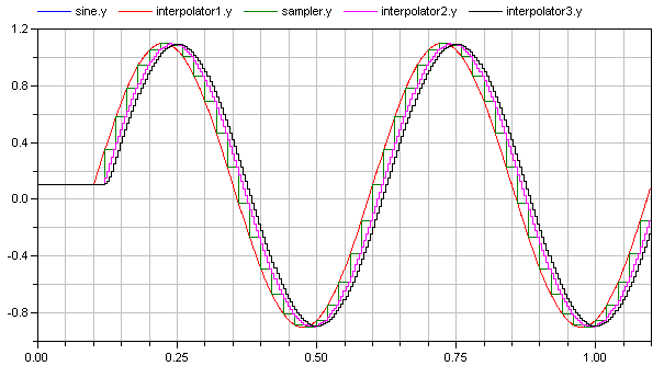
- A "sine" signal (= blue and red curve in the figure below) is
sampled with 20*Ts (= green curve in the figure below) where Ts is
the sample time of 1 ms.
- This "sine" signal is interpolated with "interpolator1" which
has a "continuous" blockType. In this case, the interpolator just
passes the input signal (y = u) and therefore the signal is
identical to the sine signal (therefore the blue and the red curve
are the same).
- The sampled sine signal is interpolated with "interpolator2" to
arrive at a sample time of 4*Ts (= violet curve in the figure
below). This gives a 20*Ts delay and a sine signal sampled with
4*Ts (instead of 20*Ts).
- In order to remove frequencies introduced by the interpolation,
"interpolator3" additionally filters the linearly interpolated
signal with a mean value filter of the same length (= black curve
in the figure below). This gives an additional delay (= a total
delay of 24*Ts), but results in a filtered interpolation
signal.
Generated at 2026-04-14T18:18:34Z by OpenModelicaOpenModelica 1.26.3 using
GenerateDoc.mos