
modelI2cBus
Extends from Modelica.Icons.Example (Icon for runnable examples).
Information
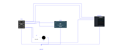
The circuit of Examples.I2c.Echo (write of Hello I2C to the echo at 0x42, read back, register read behind a repeated START), plus a logic analyser probe: CH0 on SCL, CH1 on SDA, CH2 on the indicator GP7.
The SCL channel is a plain Logic channel; the SDA channel is of kind I2cSda and names its clock channel (ch1ClockChannel = 0). In I2cBus.analyzer.txt, each transaction gives one line in hexadecimal + ASCII (S [42 W] 48 65 6C 6C 6F 20 49 32 43 P; * after a byte not acknowledged, as the last byte of a read), then a frame of the timing diagram with the bits read on each rising edge of SCL, the acknowledgements (A, N), the repeated START (Sr) and the STOP (P). The indicator lights up at the end of the last transaction.
Components
| Type | Name | Default | Description |
|---|---|---|---|
| MCU | mcu | scriptPath = Resources/Scripts/MCU/i2c_echo.py | |
| MicroPythonMCU.Peripherals.I2cEchoDevice | echo | Echo at address 0x42, carrying the pull-up resistors of the bus | |
| Modelica.Electrical.Analog.Basic.Ground | ground | ||
| Modelica.Electrical.Analog.Basic.Resistor | r7 | limits the current of led7 (GP7) | |
| MicroPythonMCU.Peripherals.LED | led7 | GP7: lights up if the three I2C exchanges are as expected | |
| MicroPythonMCU.Peripherals.Analyzers.LogicAnalyzer | analyzer | CH0 = SCL (Logic, clock of CH1), CH1 = SDA (I2cSda), CH2 = indicator GP7 (Logic) |