
modelUartLink
Extends from Modelica.Icons.Example (Icon for runnable examples).
Information
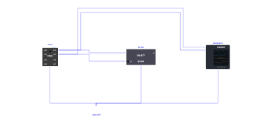
The circuit of Examples.Uart.Format (serial link in 8E2 with an echo device), plus a logic analyser probe (Peripherals.Analyzers.LogicAnalyzer) whose two first channels are clipped onto the two wires of the link: CH0 = TX (what the microcontroller transmits), CH1 = RX (what the device sends back). Both are of kind Uart, with the format of the link: 1200 baud, 8 data bits, even parity, 2 stop bits; the other channels are Off.
At the end of the simulation, the probe writes UartLink.analyzer.txt in the simulation folder (full path in the log) and opens it in Notepad: the bytes of Hello, parity! in hexadecimal + ASCII for each direction, then the ASCII timing diagram of both wires, each frame bit by bit (S start, data bits, P parity, s stop) above its byte. The echo comes back while the message is still being sent: the two directions overlap.
It also writes UartLink.analyzer.vcd, to be opened in PulseView (analyzer.openPulseView = true) with its UART decoder. Examples.Analyzer.UartErrors shows the same link with a misconfigured device.
Components
| Type | Name | Default | Description |
|---|---|---|---|
| MCU | mcu | scriptPath = Resources/Scripts/MCU/uart_format.py | |
| MicroPythonMCU.Peripherals.UartEchoDevice | echo | Sends back each received byte, in 8E2 like the microcontroller | |
| Modelica.Electrical.Analog.Basic.Ground | ground | ||
| MicroPythonMCU.Peripherals.Analyzers.LogicAnalyzer | analyzer | CH0 on the transmit wire of the microcontroller, CH1 on its receive wire, both decoded as UART 1200 baud 8E2 |