
modelGroveLcd
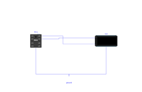
Extends from Modelica.Icons.Example (Icon for runnable examples).
Information
The microcontroller runs an existing MicroPython driver for the Grove - LCD RGB Backlight screen (Scripts/MCU/driver_grove_lcd_rgb.py, © 2019 Christophe Gueneau), whose class GroveLcd_RGB has undergone no modification. As on the real board, the driver is a module placed next to the main program (Scripts/MCU/i2c_grove_lcd_rgb.py), which imports it with from driver_grove_lcd_rgb import GroveLcd_RGB — importable thanks to mcu.addScriptDirToPath, enabled by default. The driver creates its bus with I2C(scl=Pin(4), sda=Pin(5), freq=20000), initialises the screen (function set sequence, display on, clear), then loops: "hello World" on line 1 from column 2, and red, green, blue backlight, 500 ms each.
This demonstrates the digital twin approach: the same code runs on the real board and in the simulation. The I2cGroveLcdRgb component does not know this driver; it emulates the two chips of the module from their datasheets, based on the bytes actually decoded on the bus.
To watch during the animated replay: the text and colour of the lcd icon; mcu.GP4.v (SCL) and mcu.GP5.v (SDA), which show the frames at 20 kHz (one character = 3 bytes, about 1.5 ms); the simulation log, which lists each write received by the screen with its address and bytes.
Components
| Type | Name | Default | Description |
|---|---|---|---|
| MCU | mcu | scriptPath = Resources/Scripts/MCU/i2c_grove_lcd_rgb.py - main program, which imports the driver driver_grove_lcd_rgb.py placed next to it ((c) 2019 Christophe Gueneau, unchanged) | |
| MicroPythonMCU.Peripherals.I2cGroveLcdRgb | lcd | 16x2 screen with RGB backlight (JHD1313 at 0x3E, PCA9633 at 0x62), carrying the pull-ups of the bus | |
| Modelica.Electrical.Analog.Basic.Ground | ground |